How to Wire a Drone: Complete Soldering Guide for Beginners
Bad solder joints cause mid-air failures. Good joints keep your drone flying. Here's the complete guide to wiring and soldering your DIY drone build.
Bad solder joints cause mid-air failures. Bullet connectors vibrate loose, increase resistance, and fail under stress. Soldering creates a permanent, metallurgical bond with minimal resistance and maximum strength.
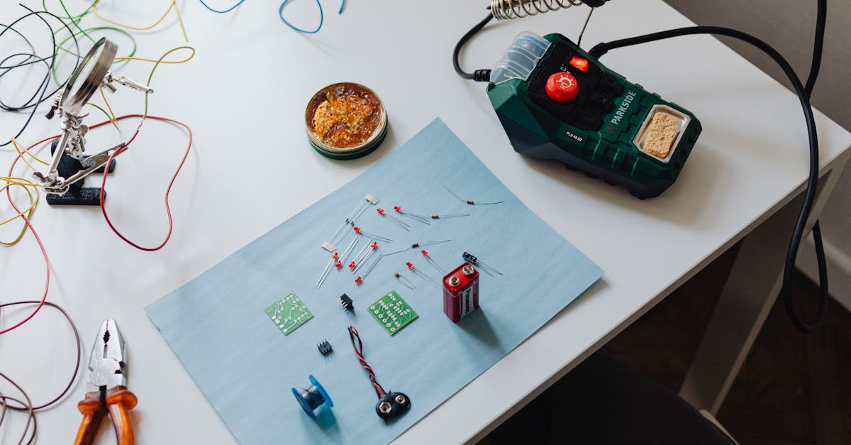
Tools You Need
- Soldering iron — Pinecil or TS100 (affordable, temperature-controlled, USB-C powered)
- Rosin-core solder — 60/40 leaded melts easily and flows well
- Flux pen or paste — The secret ingredient that helps solder flow
- Wire stripper — For clean wire prep without nicking strands
- Heat shrink tubing — Assorted sizes for insulating joints
- Helping hands — Holds wires steady while you solder
- Desoldering braid — For fixing mistakes
- Safety glasses and ventilation — Always
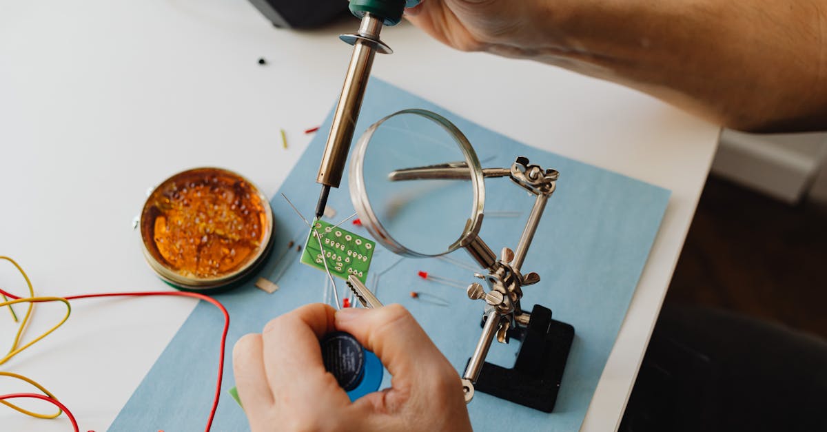
Basic Soldering Technique
- Clean and tin the iron tip — Wipe on damp sponge or brass wool
- Apply flux to the pad or wire
- Heat the pad, not the solder — Touch iron to both pad and wire
- Apply solder to the heated joint — It flows toward heat naturally
- Remove solder first, then iron
- Let it cool naturally — Don’t blow on it
Good joint: Shiny, smooth cone that hugs the wire tightly.
Bad joint: Dull, rough blob sitting on top of the pad like water on a waxed car. Must be re-done.
Wiring Sequence
Step 1: ESC Power to PDB
Solder ESC power wires to the Power Distribution Board — positive to positive, negative to negative.
Step 2: Motors to ESCs
Three wires per motor to each ESC. If a motor spins wrong direction later, desolder any two wires and swap them.
Step 3: Battery Connector
Solder XT60 connector using thick 10-12 AWG wire. Keep leads short. These joints carry massive current.
Step 4: ESC Signal to Flight Controller
Solder signal wires from each ESC to the corresponding motor pads on the FC. These are delicate — use lower heat.
Step 5: Receiver to FC
Connect signal, power, and ground wires from receiver to the correct channels.
Step 6: Accessories
GPS module, buzzer, LED strip — solder to appropriate pads on the FC.
Common Mistakes
- Cold joints — Iron too cold or didn’t heat the pad enough. Solder sits on top without bonding.
- Too much solder — Creates blobs that bridge adjacent pads and cause shorts.
- No flux — Solder balls up and refuses to stick. Always use flux.
- No heat shrink — Bare joints + carbon fiber frame = short circuit on crash.
Heat Shrink Everything
Every exposed solder joint needs heat shrink tubing. Slide the tube onto the wire before soldering. After the joint cools, slide it over and apply heat. This prevents shorts from vibration and crashes — when your drone hits the ground, wires shift and can touch the conductive carbon fiber frame.
Never skip this step.
Learn every connection in our hands-on free Build Your Own Drone course.